




2. BPS and AGB Processing Overview#
2.1 BPS Overview#
The BIOMASS Processing Suite (BPS) is in charge of processing BIOMASS Level-0 data up to Level-3, generating a wide set of products. Product generation is depicted in separate figures for the TOM phase and the INT phase. The processing foresees the following steps:
L1 processing: the BIOMASS image formation step, taking as input one L0 slice and generating as output N ≥ 1 L1 frames;
Stack processing: coregistration and stacking that defines the required 7-image tomographic stacks or the 3-image interferometric stacks, including stack phase calibration;
L2a processing: per-stack processing that provides inputs to tile generation performed by the L2b processors. For one global cycle the number of stacks varies mainly with latitude, approximately from a minimum of two at the Equator (ascending/descending) to about six at higher latitudes (three ascending/descending pairs);
L2b processing: aggregates all stack-based L2a products over the same ground location (tile) in the same time interval and generates a single BIOMASS L2b product. The number of stacks available per DGG tile varies based on tile dimensions and swath coverage [RD8];
L3 processing: consolidation processing removing discontinuities in L2b products.
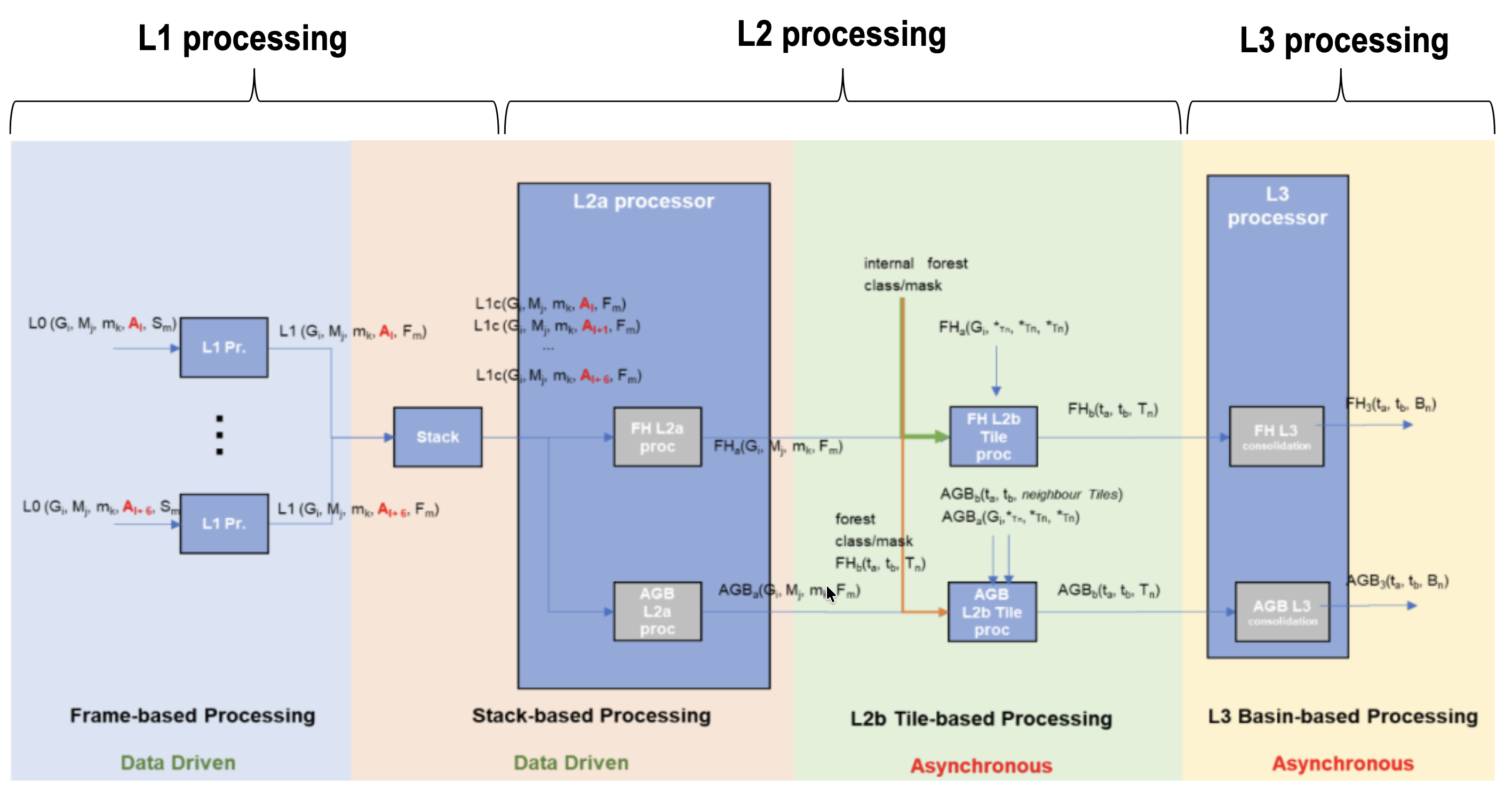
Fig. 1 — Biomass high-level processing scheme from L0 data to L3 products, TOM phase.
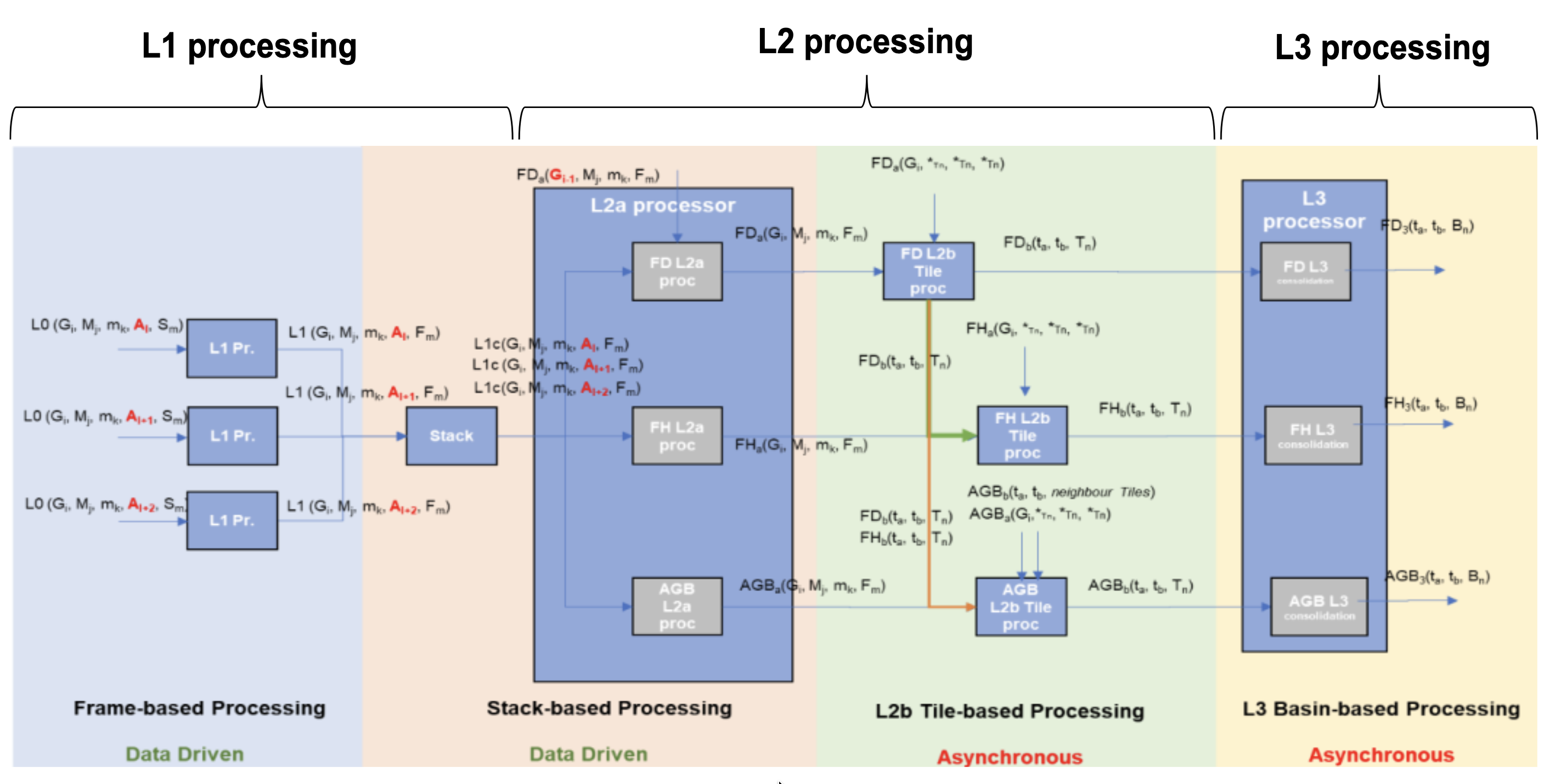
Fig. 2 — Biomass high-level processing scheme from L0 data to L3 products, INT phase.
2.2 AGB Processing Overview#
The AGB processing has as main goal the generation of maps of above ground biomass density at a spatial resolution roughly equivalent to ~200 m × 200 m (i.e. 4 ha) at the Equator [AD2]. It receives as input a stack of BIOMASS Level-1c images (SCS co-registered and calibrated stack), including its relevant annotated data [AD3]. The AGB processing is divided into three levels:
L2a, generates a ground cancelled GN product, corresponding to L1 acquisitions filtered in order to attenuate ground scattering and enhance canopy scattering; interferometric diversity is used to perform filtering, so that only polarimetric diversity remains after filtering;
L2b, generates above ground biomass density map from all the L2a products on a connected group of DGG tiles, as well as a quality map, training on external reference AGB [RD10];
L3, consolidates the result removing discontinuities in L2b products.
Note
Provided that FD algorithm proper validation will only be possible with BIOMASS in orbit, the strategy proposed to deal with FH/AGB dependency on FD is to initially input to FH/AGB a forest/non-forest mask generated outside of BPS [AD1] [AD2]. After testing FD performance with BIOMASS in orbit, FD dependency can be switched on again, provided it has a satisfactory performance. The diagram of Fig.2 reports nonetheless FD input for completeness.
Note
L2 processor receives from Stack processor L1c products with two co-polarization (CP) channels and one cross-polarization (XP) channel. Details on the aggregation of XP channels into one XP are reported in [RD1].
Note
Regarding stack images cardinality, their number can vary (not always 3 or 7) due to contingency reasons and it can go up to 8 in TOM phase.
2.3 AGB Processing Workflow and Algorithmic Overview#
The main steps of the AGB processing workflow are depicted in the following figure and described in detail in the following sub-sections. This algorithm is a tailoring of the one described in [RD11].
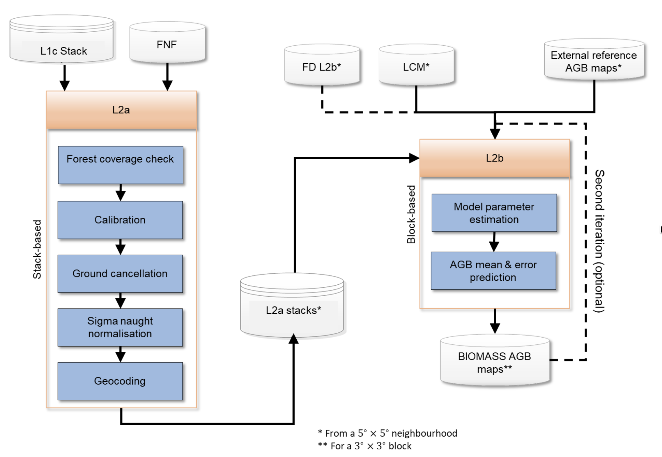
Fig. 3 — AGB processing detailed workflow. 5°x5° neighbourhood and 3°x3° processing block are shown in Fig.12.
2.3.1 Ground cancellation (L2A_P)#
The main steps of the stack-based L2a block are:
forest coverage check: predetermine which input data (as a whole image) should need to be processed;
calibration: application of phase calibration and ground steering (terrain at zero elevation) screens to the stack;
ground cancellation: removes the contribution of the ground scattering from the stack;
sigma naught calibration: removes the first-order dependence on incidence angle and normalizes to resolution cell area;
geocoding: projects the processed data on a geographic map, accounting for the different forest point locations with respect to the reference DEM.
2.3.2 Above-ground biomass density estimation (L2B_AGB_P)#
The main steps of the L2b block are:
selection of training data: checking for availability of training AGB data within the L2a stacks and selecting the appropriate source (either external reference AGB data or previous version of the BIOMASS AGB map);
training data extraction: extracting data from the extent of a tile and its neighborhood, matching pixels with reference AGB and forest type information with pixels from L2a stacks;
parameters estimation: estimating AGB model parameters;
AGB mean and standard error estimation: extracting L2a stack data within the current tile and creating maps of AGB mean and standard error.
2.3.3 Note on interpretation of inputs and outputs tables#
Inputs and outputs for each processing sub-step are summarised in specific subsections (two subsections for each sub-step). A specific tabular format is defined to improve access to the document. The meaning of each column is exemplified in the following table.
Column |
Meaning |
|---|---|
Symbol |
Mathematical symbol of the quantity appearing in formulas |
Name |
Name of the quantity as related to other BPS documentation (e.g. AUX_FMT, L1 ATBDs) |
Origin / Destination |
BPS document name describing the origin of the quantity, processing step, or destination product |
Size |
Dimensions of the quantity |
Variability |
Range of values or update rate of an internal resource |
Default |
Default value for configuration parameters |
Description |
Verbal description of the quantity and its characteristics (e.g. measurement units) |