




4. L2a Products Format Specification#
4.1 Main Product Header#
The Main Product Header (MPH) is an XML file present in all the BIOMASS L2 products.
BIOMASS L2 products are folder based and the MPH is top level leaf of the product tree.
The MPH main scope is to provide all the information related to the:
Genesis of the product;
Identification of the product for example for cataloguing purposes;
Product consistency (filesize).
It must be noted that, while the footprint is inherited from lower level products (thus vertices represent the extent of the acquired data), DGG tiles (tileId list) are related to the full extent of L2a product (that is geocoded).
For the detailed description of the MPH content and format refer to [AD3]. Here just a
schematic representation is reported, where this notation is applicable:
This is a container of other elements
This element or block of elements can occur more than one time (i.e. it is a list)
This is a container of actual metadata
This is a mandatory element for the standard which is left empty by this specification
This element or block of elements is optional
bio:EarthObservation Root element of metadata representation tailored for BIOMASS SAR products
om:phenomenonTime Time coverage of the product
gml:TimePeriod Time coverage of the product as a period
gml:beginPosition Start date and time of the product
gml:endPosition Stop date and time of the product
om:resultTime Time when the sensing data has become available
gml:TimeInstant Identifiable position in time
gml:timePosition Date and time of data availability
om:validTime Time validity of the product
gml:TimePeriod Time validity of the product as a period
gml:beginPosition Validity start date and time of the product
gml:endPosition Validity stop date and time of the product
om:procedure Procedure used to sense the data
eop:EarthObservationEquipment Equipment used to sense the data
eop:platform Platform description
eop:Platform Nested element for platform description
eop:shortName Satellite name
eop:instrument Instrument description
eop:Instrument Nested element for instrument description
eop:shortName Sensor name
eop:sensor Sensor description
eop:Sensor Nested element for sensor description
eop:sensorType Sensor type
eop:operationalMode Sensor operational mode
eop:swathIdentifier Swath identifier
eop:acquisitionParameters Acquisition parameters
bio:Acquisition Acquisition description
eop:orbitDirection Orbit direction
eop:wrsLongitudeGrid Track number
eop:wrsLatitudeGrid Frame number
sar:antennaLookDirection SAR antenna look direction
bio:missionPhase BIOMASS mission phase
bio:globalCoverageID BIOMASS global coverage identifier
bio:majorCycleID BIOMASS major cycle identifier
bio:tileID List of DGG geographic cell (tile) identifiers
bio:basinID Retrieval basin identifier
om:observedProperty Observed property (empty)
om:featureOfInterest Observed area
eop:Footprint Footprint description
eop:multiExtentOf Footprint representation structure, coordinates in posList
gml:MultiSurface
gml:surfaceMember
gml:Polygon
gml:exterior
gml:LinearRing
gml:posList Footprint points in NE,SE,SW,NW,NE order
eop:centerOf Acquisition centre representation structure
gml:Point
gml:pos Coordinates of the centre of the acquisition
om:result Observation result
eop:EarthObservationResult
eop:product
bio:ProductInformation
eop:fileName
ows:ServiceReference Product filename
ows:RequestMessage download request (empty)
eop:version Product baseline
eop:product (list)
bio:ProductInformation
eop:fileName
ows:ServiceReference Product filename (internal files)
ows:RequestMessage download request (empty)
eop:size Product size
bio:rds Product schema
eop:metaDataProperty Observation metadata
bio:EarthObservationMetaData
eop:identifier Product identifier
eop:doi Digital Object Identifier
eop:acquisitionType Type of acquisition
eop:productType Product type
eop:status Status of the product
eop:processing Data processing information
bio:ProcessingInformation
eop:processingCenter Processing centre code
eop:processingDate Processing date and time
eop:processorName Processor name
eop:processorVersion Processor version
eop:processingLevel Processing level
eop:auxiliaryDataSetFileName Auxiliary DS filename
eop:processingMode File Class
bio:sourceProduct BIOMASS source product identifier
bio:refDoc Reference document
Main product header L2a (metadata schematic representation)
4.2 Measurement Data Sets (MDS)#
The MDS of the L2a product is obtained by processing L1c images at the given Global cycle, along with the processing results from the previous Global cycle and it is composed by three images, each organised in separated Cloud Optimized GeoTIFF (COG) files [RD1]:
the probability of change, being the quality layer, which identifies changes in areas at a given Global cycle; each pixel of the probability raster is a real value from 0 to 1, coded using a 4-byte float per pixel (float32);
the forest disturbance is a binary classification of intact/deforested areas, coded using a 1-byte per pixel (ubyte);
the CFM image is a mask computed from the CFM inside L2a product of previous Global Cycle and given as input, or from the FNF in input if it is first Global Cycle; basing on the forest disturbance MDS and coded using a 1-byte per pixel (ubyte).
A Cloud Optimized GeoTIFF (COG) is a regular GeoTIFF file, aimed at being hosted on a
HTTP file server, with an internal organization that enables more efficient workflows on the
cloud. It does this by leveraging the ability of clients issuing HTTP GET range requests to ask for just the parts of a file they need.
The COG format is natively supported by GDAL library [RD2] [RD3] and by libraries and tools based on GDAL library (Dask and Rasterio packages for Python, …).
The MDS images ground coverage is corresponding to the geocoded spatial stack coverage of input L1c used to compute L2a product: the L2a MDS images are geocoded to the minimum required latitude-longitude coverage to accommodate for the product on ground, following the same sampling requirements specified in [RD9], ensuring a ground sampling always better than the resolution.
Compression strategy
MDS is composed by real and binary images: it is possible to introduce with benefit a strategy for data compression making use of native LibTIFF libraries capabilities [RD4]; depending on the data type, the strategy will be a GeoTIFF LERC+ZSTD compression for the real data and a ZSTD only (loss-less) for the binary one, in details:
LERC compression algorithm, for the real data only, can be configured to decide how lossy the compression will be, through the “
MAX_Z_ERROR” option (loss-less only if set to zero);ZSTD compression algorithm, for both data types, with a configurable compression level from 0 to 9 (loss-less), where zero means no compression.
Both set by configuration: more details in sec. Tab.19.
Metadata
The TIFF and GeoTIFF tags used to annotate the MDS files are described in the following table. For the complete description of each tag refer to official TIFF format documentation [RD5] and official GeoTIFF documentation [RD11]
Table 2 — MDS – TIFF and GeoTIFF tags
Tag Name |
Code |
Value |
Description |
|---|---|---|---|
ImageWidth |
256 |
Variable |
Number of columns in the image, i.e. the number of pixels per row. |
ImageLength |
257 |
Variable |
Number of rows of pixels in the image. |
BitsPerSample |
258 |
32 or 8 |
Number of bits per component. |
Compression |
259 |
34887, 34926 |
Compression scheme used on the image data (LERC and ZSTD) |
PhotometricInterpretation |
262 |
1 |
Colour space of the image. Always set to 1 (minimum value is black). |
ImageDescription |
270 |
Variable |
A string that describes the image. Valid Strings are composed by prefix: “BIOMASS L2a FP_FD__L2A: ” or “BIOMASS L2b FP_FD__L2B: ” and: “Probability of change” “Computed forest mask” “Forest Disturbance” “Heat Map” (L2b only) “acquisition id image” (L2b only) |
SamplesPerPixel |
277 |
1 |
The number of components per pixel. Always set to 1, since each product is stored in a different file. |
PlanarConfiguration |
284 |
1 |
How the components of each pixel are stored. Always set to 1 (contiguous). |
Software |
305 |
Variable |
Software name and version that created the image. |
DateTime |
306 |
Variable |
Date and time of image creation in the format: YYYY:MM:DD HH:MM:SS |
TileWidth |
322 |
Variable |
The tile width in pixels. This is the number of columns in each tile. |
TileLength |
323 |
Variable |
The tile length (height) in pixels. This is the number of rows in each tile. |
TileOffsets |
324 |
Variable |
For each tile, the byte offset of that tile, as compressed and stored on disk. |
TileByteCounts |
325 |
Variable |
For each tile, the number of (compressed) bytes in that tile. |
SampleFormat |
339 |
3 or 1 |
Specifies how to interpret each data sample in a pixel. Set to 3 (IEEE floating point data) or 1 (unsigned integer data). |
ModelPixelScaleTag |
33550 |
Variable |
List of doubles, (ScaleX, ScaleY, ScaleZ) where ScaleX and ScaleY give the horizontal and vertical spacing of raster pixels. The ScaleZ is zero. |
ModelTiePointTag |
33922 |
N * (pixel, line, 0, lat, long, 0) |
Maps image pixels to geographic coordinates, where N is the number of tie points in the scene. |
GeoKeyDirectoryTag |
34735 |
Variable |
Contains the value of all GeoTIFF keys of type SHORT and the location of the values for GeoTIFF keys of other types. |
GeoDoubleParamsTag |
34736 |
Variable |
Contains the value of all GeoTIFF keys of type DOUBLE. |
GeoAsciiParamsTag |
34737 |
Variable |
Contains the value of all GeoTIFF keys of type ASCII. |
|
42112 |
Variable |
Contains GDAL metadata (see table below) |
|
42113 |
“-9999.0” or “255” |
Pixel value used in case of invalid data. ASCII string encoded value. (See 3) |
LercParameters |
50674 |
Variable |
LERC compression parameters: version, additional compression. e.g. 4,2 for LERC v4 with ZSTD Not present in binary tiffs (FD and CFM) |
Predictor |
317 |
Variable |
Integer of value “1” ( |
The GDAL_METADATA tag content is listed in the following table
Table 3 — MDS – GDAL_METADATA tiff tag content
Tag Name |
Value |
Description |
|---|---|---|
basinID |
list of strings |
List of DGG basin identifiers (for querying purposes). More than one ID in case of tile covering more than one geographic location. Private Tag code. |
|
float |
Absolute maximum error present in the image data, due to LERC compression. Private Tag code. |
Swath |
string |
Image swath. Private Tag code (L2A only) |
tileID |
list of strings |
List of DGG geographic cell (tile) identifiers (for querying purposes). Private Tag code. |
Overviews
The exploitation of GDAL library allows to easily add to COG file one or more overviews of the L2 image.
Overviews are sub-sampled versions of an L2 image. Adding one or more overviews at different resolution levels allows to use pyramidal viewers directly on L2 image file, without the need of transcoding operations or of further processing.
The following (minimum) number of overviews is foreseen:
multi-look factors (latitude x longitude) of 2x2.
multi-look factors (latitude x longitude) of 4x4.
4.3 Annotation data sets (ADS)#
4.3.1 Main ADS#
This section describes in details the content of main ADS for L2a products.
An overview is provided by figure and table below.
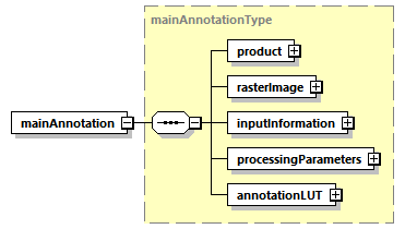
Fig. 3 — Main L2a ADS
Table 4 — Main L2a ADS
Name |
Description |
Data Type |
Cardinality |
|---|---|---|---|
product |
Product L2a DSR. This DSR contains the L2a product information. |
|
1 |
|
Raster image DSR. This DSR contains all the necessary information to exploit the L2a product raster images. |
|
1 |
InputInformation |
Input Information DSR. This DSR contains the necessary information to identify the input data set to the L2a processing. |
InputInformationL2aType |
1 |
|
Processing parameters DSR. This DSR contains the description of L2a processing parameters. |
|
1 |
annotationLUT |
Annotation LUT DSR. This DSR contains the list of Look-Up Tables (LUTs) complementing product main annotations. |
|
1 |
The content of each DSR is described making use of tables as the one here above. All the tables share the same structure and are filled following the same conventions, i.e.:
Name: defines the name of the element or attribute;
Description: describes the purpose of the element or attribute including the units (if applicable). The absence of a unit designation for string data types implies a string literal and for numerical data types (integers, floats, etc.…) the absence of a unit designation implies an absolute number;
Data Type: defines the data type of the element or attribute;
Cardinality: for elements, this column defines the number of occurrences of the element in the form
minOccurs..maxOccurs; for attributes, “optional” means the attribute may or may not be present and “required” means the presence of the attribute is mandatory.
In general, elements are displayed in normal font, attributes are displayed in italics.
Data types requiring a dedicated definition table are underlined, for all the others the common reference is sec. 7.1.1.
4.3.1.1 Product L2a DSR#
This DSR contains the parameters to describe the L2a product.
An overview is provided by figure and table below.
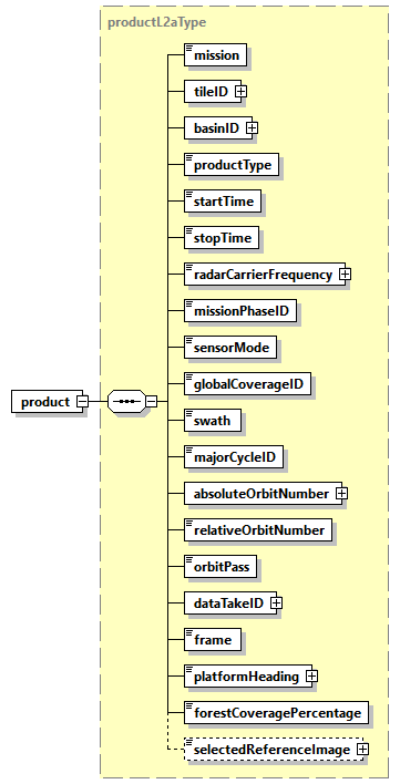
Fig. 4 — Product L2a DSR (productL2aType)
Table 5 — Product L2a DSR (productL2aType)
Name |
Description |
Data Type |
Cardinality |
|---|---|---|---|
mission |
Mission (BIOMASS). |
|
1 |
tileID |
List of DGG geographic cell (tile) identifiers. |
|
1 |
basinID |
List of DGG Basin identifiers. |
|
1 |
|
Product type (“ |
|
1 |
|
Start time of the product image [UTC]. |
|
1 |
|
Stop time of the product image [UTC]. |
|
1 |
|
Radar carrier frequency [Hz]. |
|
1 |
|
Mission phase identifier. |
|
1 |
|
Sensor mode (always Measurement). |
|
1 |
|
Global coverage identifier. |
|
1 |
swath |
Swath (S1, S2, S3). |
|
1 |
|
Major cycle identifier. |
|
1 |
|
List of absolute orbit numbers at start time (one for each input L1c). |
|
1 |
|
Relative orbit number (track) at start time. |
|
1 |
|
Orbit pass (Ascending, Descending). |
|
1 |
|
List of data take identifiers (one for each input L1c). |
|
1 |
frame |
Frame identifier. |
|
1 |
|
Platform heading relative to North [deg]. |
|
1 |
|
Forest coverage of the input STA products, compute as a percentage of all the pixels in the STA footprint. |
double |
1 |
|
Index of the input STA acquisition selected as optimal reference image (guaranteeing the widest scene coverage),used during ground cancellation. Optional element, present only when ground cancellation is performed (FD, GN) and |
|
0,1 |
Table 6 — stringListType
Name |
Description |
Data Type |
Cardinality |
|---|---|---|---|
ID |
Tile identifier string |
string |
1 … unbounded |
Table 7 — integerListType
Name |
Description |
Data Type |
Cardinality |
|---|---|---|---|
val |
Integer value |
uint32 |
1 … unbounded |
Table 8 — selectedReferenceImageType
Name |
Description |
Data Type |
Cardinality |
|---|---|---|---|
acquisitionID |
Acquisition folder name, to better identify the input image referred by the integer value. |
|
1 |
|
Zero based Integer value of the selected reference image, based on the image reading order. |
|
1 |
4.3.1.2 Raster Image DSR#
This DSR contains all the necessary information to exploit the raster images of the product. An overview is provided by figure and table below.
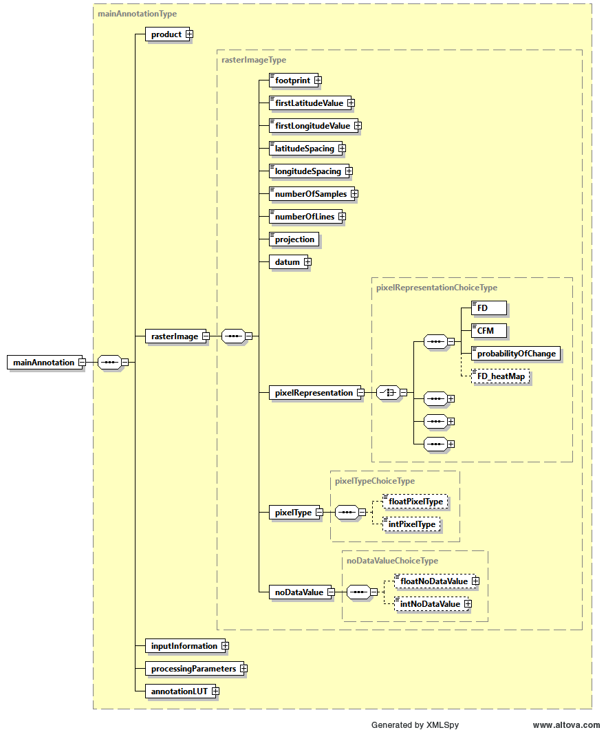
Fig. 5 — Raster image DSR (rasterImageType)
Table 9 — Raster image DSR (rasterImageType)
Name |
Description |
Data Type |
Cardinality |
|---|---|---|---|
footprint |
Image footprint, expressed as a list of latitude, longitude tuples in NE, SE, SW, NW order [deg]. |
|
1 |
|
First latitude value of the image [deg]. |
|
1 |
|
First longitude value of the image [deg]. |
|
1 |
|
Latitude spacing between samples [deg]. |
|
1 |
|
Longitude spacing between samples [deg]. |
|
1 |
|
Total number of samples in the image. |
|
1 |
|
Total number of lines in the image. |
|
1 |
projection |
Projection of the image: “Latitude longitude based on DGG”. |
|
1 |
datum |
Datum used during processing. |
|
1 |
|
Representation of the image pixels within the image MDS. |
|
1 |
|
Data type of output pixels within the image MDS. |
|
1 |
|
Pixel value in case of invalid data. The value is always set to -9999.0 float32 or 255 ubyte, depending on data type, see sec. 3. |
|
1 |
Table 10 — pixelRepresentationChoiceType (only L2a/L2b FD choice described here)
Name |
Description |
Data Type |
Cardinality |
|---|---|---|---|
FD |
Representation of the image pixels within the image MDS: Forest Disturbance |
|
1 |
CFM |
Representation of the image pixels within the image MDS: Computed forest mask |
|
1 |
|
Representation of the image pixels within the image MDS: Probability of change |
|
1 |
|
Representation of the image pixels within the image MDS: Heat Map (Only L2b) |
|
0,1 |
Acquisition_Id_Image |
Representation of the image pixels within the image MDS: acquisition_id_image (Only L2b) |
|
0,1 |
Table 11 — pixelTypeChoiceType
Name |
Description |
Data Type |
Cardinality |
|---|---|---|---|
|
Data type of output pixels within the image MDS: 32 bit Float |
|
1 |
|
Integer data type of output pixels within the image MDS: 8 bit Unsigned Integer |
|
1 |
Table 12 — noDataValueChoiceType
Name |
Description |
Data Type |
Cardinality |
|---|---|---|---|
|
Pixel value in case of invalid data. The value is always set to -9999.0 |
|
1 |
|
Pixel value in case of invalid data. The value is always set to 255 |
|
1 |
4.3.1.3 Input Information DSR#
This DSR contains information about the L1c acquisitions in input to the L2a processor.
An overview is provided by figures and tables below.
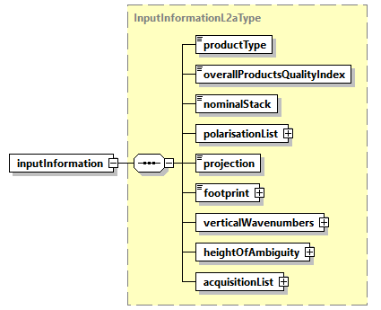
Fig. 6 — Input Information DSR (InputInformationL2aType)
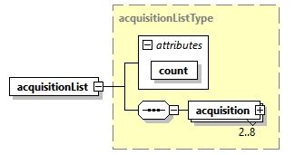
Fig. 7 — Input Information DSR, acquisition list detail (acquisitionListType)
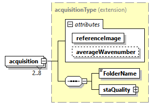
Fig. 8 — Input Information DSR, acquisition detail (acquisitionType)
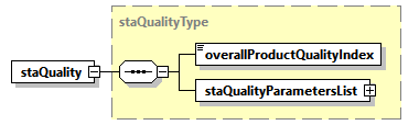
Fig. 9 — Input information DSR, staQualityType
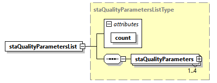
Fig. 10 — Input information DSR, staQualityParametersListType
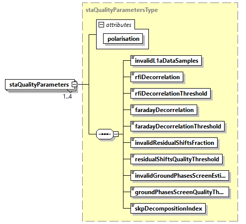
Fig. 11 — Input information DSR, staQualityParametersType
Table 13 — Input Information DSR (InputInformationL2aType)
Name |
Description |
Data Type |
Cardinality |
|---|---|---|---|
|
Input product type: always “STA” (L1c STA). |
|
1 |
|
Quality index based on the “ |
|
1 |
|
True if it is a nominal stack (3 STA products for INT phase or 7 STA products for TOM phase), False otherwise |
bool |
1 |
|
List of polarisations composing input L1c data: for each polarisation it is also specified, with an attribute, the decorrelation factors due to RFI strength. |
|
1 |
projection |
Projection of the input acquisitions, always “Slant Range”. |
|
1 |
footprint |
Image footprint of all the acquisitions composing the stack, expressed as a list of latitude, longitude tuples in NE, SE, SW, NW order [deg]. |
|
1 |
|
Minimum and maximum values of the vertical wavenumbers [rad/m] in the read and used Input STA products. |
|
1 |
|
Minimum and maximum values of the height of ambiguity (HoA) [m], computed from the vertical wavenumbers in the read and used Input STA products. |
|
1 |
|
Info about acquisition of the stack. |
|
1 |
The acquisitionListType is composed by 2 to 8 entries, where each entry is an L1c acquisition folder name string, as defined in [RD10] (or a couple of images for the images pair selection for ground cancellation, 4.3.1.4)
Table 14 — Input information DSR (acquisitionListType)
Name |
Description |
Data Type |
Cardinality |
|---|---|---|---|
count |
Number of acquisitions. |
|
required |
acquisition |
Info about acquisition of the stack. |
|
2…8 |
Table 15 — Input information DSR (acquisitionType)
Name |
Description |
Data Type |
Cardinality |
|---|---|---|---|
|
Flag to indicate if this is the reference image or not. |
bool |
1 |
|
Average Wavenumber |
float |
1 |
FolderName |
Folder name which univocally identifies an acquisition of the stack. |
|
1 |
|
Folder name which univocally identifies an acquisition of the stack, as defined in [RD10] |
|
1 |
Table 16 — Input information DSR (staQualityType)
Name |
Description |
Data Type |
Cardinality |
|---|---|---|---|
|
Overall product quality index. This annotation is calculated based on specific quality parameters and gives an overall quality value to the product. Equal to 0 for valid products and to 1 for invalid ones. |
|
1 |
|
Quality parameters list. The list contains an entry for each output product’s polarisation. |
|
1 |
Table 17 — STA quality DSR (staQualityParametersListType)
Name |
Description |
Data Type |
Cardinality |
|---|---|---|---|
count |
|
required |
|
|
Quality parameters for the current polarisation. |
|
1 … 4 |
Table 18 — STA quality DSR (staQualityParametersType)
Name |
Description |
Data Type |
Cardinality |
|---|---|---|---|
polarisation |
|
required |
|
|
Number of invalid L1a data samples (according to their mean and standard deviation), expressed as a normalized fraction of the total number of samples. The value is between 0 and 1. |
|
1 |
|
Decorrelation factor due to RFI strength. The value is between 0 and 1. |
|
1 |
|
Maximum decorrelation factor due to RFI strength admissible to use the image as the primary image. The value is between 0 and 1 and copied from the AUX-PPS. |
|
1 |
|
Decorrelation factor due to Faraday residual. The value is between 0 and 1. |
|
1 |
|
Maximum decorrelation factor due to Faraday residual admissible to use the image as the primary image. The value is between 0 and 1 and copied from AUX-PPS. |
|
1 |
|
Number of invalid residual coregistration shifts, expressed as a normalized fraction of the total number of residual coregistration shifts. The value is between 0 and 1. |
|
1 |
|
Threshold on residual coregistration shifts quality. The value is between 0 and 1 and copied from AUX-PPS. Residual shifts with a quality lower than this threshold are not used for processing. |
|
1 |
|
Number of invalid ground phase screen estimates, expressed as a normalized fraction of the total number of ground phase screen estimates. The value is between 0 and 1. |
|
1 |
|
Threshold on ground phase screen estimation quality. The value is between 0 and 1 and copied from the AUX-PPS. Estimates with a quality lower than this threshold are not corrected. Used only in case |
|
1 |
|
Error code for the SKP decomposition. Positive if the SKP decomposition hit a nonblocking contingency case (e.g. SVD decomposition failure etc.) and the exported SKP-related LUTs contain values obtained from a contingency handling procedure. 0 otherwise. |
|
1 |
Table 19 — Input information DSR (polarisationListType)
Name |
Description |
Data Type |
Cardinality |
|---|---|---|---|
count |
|
required |
|
polarisation |
Polarisation (HH, VH, VV). |
|
3 |
4.3.1.4 Processing parameters L2a DSR#
This DSR contains the exhaustive list of L2a Forest Disturbance processing parameters applied. An overview is provided by figure and table below.
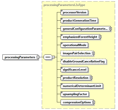
Fig. 12 — Processing parameters L2a DSR (processingparametersL2aType)
Table 20 — Processing parameters L2a DSR (processingparametersL2aType
Name |
Description |
Data Type |
Cardinality |
|---|---|---|---|
|
Version of the processor used to generate the product. |
|
1 |
|
Product generation time [UTC]. |
|
1 |
|
General processing flags (not specific to the Forest Disturbance processing). |
|
1 |
|
Value of the height [m] which has been emphasized during ground cancellation [AD8]. |
|
1 |
|
Ground Cancellation method used between the followings. “single reference”: direct computation with a preliminary automatic reference image selection. or “insar pair”: debug operational mode, perform computation with only the two images specified in the optional element |
|
1 |
|
Optional: if |
|
0…1 |
|
False, if the ground cancellation has been performed. True, if ground cancellation has been disabled. Optional, default is False. |
bool |
0…1 |
|
Significance level, expressed as a percentage, applied in the change detection algorithm [AD8]. |
|
1 |
|
Value in [m] used as the resolution on ground grange map and also to perform the covariance averaging in radar coordinates. |
|
1 |
|
Lower threshold to avoid numerical errors when computing pol covariance matrices determinants. Positive float number, |
|
1 |
|
Configurable compression options for all the L2a MDS COG and ADS NetCDF LUT variables (see 4.3.2 for LUT “ZLIB” compression details). |
|
1 |
|
Upsampling factor used during covariance computation. |
|
1 |
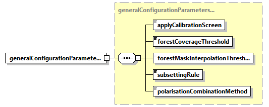
Fig. 13 — Processing parameters L2a DSR (generalConfigurationParametersType)
Table 21 — Processing parameters L2a DSR (generalConfigurationParametersType)
Name |
Description |
Data Type |
Cardinality |
|---|---|---|---|
|
Phase calibration performed: “none”: no phase screen has been applied “geometry”: only flattening phase screen has been applied (i.e., as computed from acquisition geometry) “skp”: complete phase screen has been applied (default) |
|
1 |
|
Minimum percentage forest coverage in L2a product footprint, used to trigger L2a processing. |
|
1 |
|
This parameter is a threshold which has been used to fix rounding of pixels with decimal values originated from binary FNF interpolation onto L2a grid. This created a safety buffer around forest border. |
|
1 |
|
In case of more than three acquisitions the user selected subsetting rule is here annotated (always “geometry” for FD L2a processor). |
|
1 |
|
Polarisations combination method: “HV” or “VH”, if just one of the two is selected (in addition to HH and VV ones); “Average”, if the average of HV and VH is computed and used; “None” if no combination is performed (all the four polarizations are used). |
|
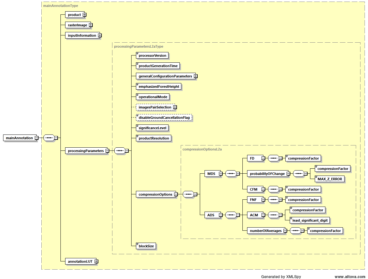
Fig. 14 — Processing parameters L2a DSR (compressionOptionsL2aType)
Table 22 — Processing parameters L2a DSR (compressionOptionsL2aType)
Name |
Description |
Data Type |
Cardinality |
|---|---|---|---|
MDS à |
|
|
1 |
MDS à |
For the probability of change image MDS, define exactly how lossy the LERC compression algorithm is allowed to be, specifying the absolute maximum error admitted. Zero means loss-less compression. |
|
1 |
MDS à FD à |
ZSTD algorithm compression factor for the FD and CFM binary images MDS. From 0 to 9, where zero means no compression. |
|
1 |
ADS àFNF à |
ZLIB algorithm compression factor for the FNF and |
|
1 |
ADS à ACM à |
ZLIB algorithm compression factor valid for all the ACM ADS LUT layers. From 0 to 9, where zero means no compression. |
|
1 |
ADS à ACM à least_significant_digit |
For all the layers of ACM LUT ADS, define exactly how lossy the ZLIB compression algorithm is allowed to be, specifying the power of ten of the smallest decimal place in the data that is a reliable value. See 4.3.2. |
|
1 |
4.3.1.5 Annotation LUT DSR#
This DSR contains the list of Look-Up Tables (LUTs) complementing product main annotations. An overview is provided by figure and table below.
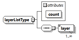
Fig. 15 — Annotation LUT DSR (layerListType)
Table 23 — Annotation LUT DSR (layerListType)
Name |
Description |
Data Type |
Cardinality |
|---|---|---|---|
count |
Number of layers. |
|
required |
layer |
LUT layer content. |
|
1 … unbounded |
4.3.2 Look-Up Tables (LUT) ADS#
This section describes in details the content of Look-Up Tables (LUT) ADS.
This ADS complements the Main ADS one, including those annotations that can be represented as 2D maps of values. This approach has been chosen in order to avoid worsening the Main ADS readability and handling, and also to provide an easier access to such information.
The format adopted for LUT ADS is NetCDF one [RD6] and in particular the used implementation is the Python NetCDF4 [RD7]. Thanks to the flexibility provided by this format, all the components of this ADS are stored in the same file.
Complex images disk storage details
Differently from other SAR missions (and from the standard way of storing SAR data), for the BIOMASS mission, complex data are stored separating amplitude and phase values of each pixel instead of its real and imaginary parts. In particular for FD, the ACM ADS is a matrix of 6 images of which three real and three complex, so in total there will be 9 layers, because the three complex images will be separated each in two different NetCDF layers:
one layer with the amplitude values of each pixel;
one layer with the phase values (radians) of each pixel.
The main rationale behind this choice stands in the products usability. Amplitude and phase representation has in fact several advantages from the users’ point of view:
ease image visualization on a map, either using a data browser on a cloud computing platform or through a GIS software on a local PC, and the generation of overviews;
run applications that exploit the amplitude only;
run fast workflows on a cloud computing platform on a custom subset of data;
speed-up applications working on all the polarisations together;
and more.
The LUT ADS provides:
external Forest/Non-Forest mask (generated outside of BPS [AD6] [AD7] [AD8] [AD9]).
ACM, averaging of the computed covariance from input L1c data stack at the given Global cycle with the previous cycle ACM from L2a given in input, with a total of 9 layers needed to store the three real images and the three complex images which are separated in amplitude and phase layers.
Number of averages, the number of ACM covariances averaged so far at given Global cycle, pixel wise.
Fig. 16 provides a schematic representation of the LUT ADS structure. Note that an XSD diagram has been used for this purpose, even if there is no link between the two formats. The ADS is organised as follows:
a series of root level Attributes, containing all those global parameters referring to the product as a whole;
a Dimensions group, where names and lengths of the dimensions used when creating data arrays are here defined;
a series of Coordinate variables, special variables to store the axis data values, for each dimension in the Dimensions group;
a series of components (groups of variables), one for each LUT stored in the ADS. Each component is composed by a group of variables which can be divided in:
the data arrays, storing the annotation Look-Up Tables themselves. A variable represents an array of values of the same data type and it is defined over two or more dimensions from the Dimensions group;
ancillary scalar variables containing other useful metadata to complete the LUT definition.
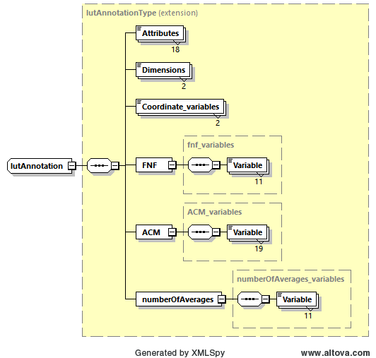
Fig. 16 — Look-Up Tables (LUT) ADS
Compression strategy
ACM LUT ADS data variable is composed by real float values, FNF is binary integer and numberOfAverages is integer. Depending on data type it is possible to introduce with benefit the following strategy for data compression making use of native Python NetCDF4 capabilities [RD7], using the ZLIB compression algorithm and featuring:
for binary data (FNF) and integer data (
numberOfAverages) a compression level from 0 to 9 (loss-less), where zero means no compression;for real float data variable (ACM) a compression level from 0 to 9 and an additional option “least_significant_digit” to decide how lossy the compression will be.
All set by configuration, more details in sec. Tab.19.
4.3.2.1 Look-Up tables detailed content#
The content of L2a LUT ADS is reported hereafter, where:
the series of Attributes contain the same list of parameters described in sec. 4.3.1.1 for the Product L2a DSR (for all the details about these parameters refer to this section);
the Dimensions group is composed by Latitude and Longitude, as the data array variables are defined in the Latitude Longitude based on DGG projection;
there are three components, FNF, ACM and
numberOfAveragesmatricesthis notation is applicable:
this is the attribute or variable name
this is the actual content of constant values over the mission
this is a description of values content which depends on the processing
LUT ADS Attributes:
mission: “BIOMASS”
tileID: [string] json encoded list of DGG geographic tile identifiers (NxxEyyy))
basinID: [string] json encoded list of DGG Basin identifiers
productType: “FP_FD__L2A”
startTime: [str: YYYY-MM-DD hh:mm:ss.ppp] Start time of the product image, UTC
stopTime: [str: YYYY-MM-DD hh:mm:ss.ppp] Stop time of the product image, UTC
radarCarrierFrequency: [float32] Radar carrier frequency [Hz]
missionPhaseID: [str: COM, TOM or INT] Mission phase identifier
sensorMode: “Measurement”
globalCoverageID: [uint16] Global coverage identifier
swath: [str: S1, S2 or S3] BIOMASS swath identifier
majorCycleID: [uint16] Major cycle identifier
absoluteOrbitNumber: [list of uint32] List of absolute orbit numbers at start time (one for each input L1c)
relativeOrbitNumber: [uint16] Relative orbit number (track) at start time
orbitPass: [str: Ascending or Descending] Orbit pass
dataTakeID: [string] json encoded list of data take identifiers (one for each input L1c)
frame: [uint16] Frame identifier
platform_heading: [float32] Platform heading relative to North, deg
forest_coverage_percentage: [float32] Forest coverage of the input STA products, compute as a percentage of all the pixels in the STA footprint
selected_reference_image Optional [uint16] Index of the input STA acquisition selected as optimal reference image (guaranteeing the widest scene coverage), used during ground cancellation. Optional element, present only when ground cancellation is performed (FD, GN) and operationalMode configuration has been set to “single reference”
acquisition_id_reference_image Optional [str] Acquisition folder name, to better identify the input image referred by the selectedReferenceImage
LUT ADS Dimensions / Coordinate variables:
Name: Latitude
size: [int] size
type: dtype(float32)
units: deg
description: LUTs latitude axis
Name: Longitude
size: [int] size
type: dtype(float32)
units: deg
description: LUTs longitude axis
LUT ADS group of variables:
Group Name: FNF
FNF group contents:
Name: FNF
dimensions: (Longitude, Latitude)
shape: ([int] x shape, [int] y shape)
type: dtype(ubyte)
description: Forest/Non-Forest mask: this is an external image, defined outside of BPS from aggregated C3S LCM, representing the initial two-dimensional mask, here defined in the same latitude-longitude based on DGG projection used for L2a images and cropped to have a coverage containing the L2a product image boundaries. It defines, for each geographical pixel, the initial presence or absence of forest.
Name: firstSample
shape: (1, 1)
type: dtype(uint32)
description: Product image MDS sample the first LUT sample corresponds to
Name: firstLine
shape: (1, 1)
type: dtype(uint32)
description: Product image MDS line the first LUT line corresponds to
Name: samplesInterval
shape: (1, 1)
type: dtype(uint32)
description: Number of product image MDS samples one LUT sample corresponds to
Name: linesInterval
shape: (1, 1)
type: dtype(uint32)
description: Number of product image MDS lines one LUT line corresponds to
Name: pixelType
shape: (1, 1)
type: <class str>
description: Data type of output LUT pixels
Name: noDataValue
shape: (1, 1)
type: dtype(ubyte)
description: Pixel value in case of invalid data. The value is always set to 255. (See 3)
Name: projection
shape: (1, 1)
type: <class str>
description: LUT projection, is the latitude-longitude based on DGG
Name: coordinateReferenceSystem
shape: (1, 1)
type: <class str>
description: Coordinate reference systems, as per WKT representation [RD7]
Name: geodeticReferenceFrame
shape: (1, 1)
type: <class str>
description: Geodetic reference frame
Group Name: ACM
group description: ACM represents the covariance history of all previous cycles (see also numberOfAverages variable): it is obtained by averaging the covariance computed with FD algorithm at the given Global cycle with the previous ACM in input to the processor [AD8]. At first Global cycle it is the current covariance. It consists of six images of which three real and three complex, stored in nine NetCDF layers as three layers for the three real images and three complex images, each split in the amplitude value layer and the phase value (radians) layer.
ACM group contents:
Name: layer1
dimensions: (Longitude, Latitude)
shape: ([int] x shape, [int] y shape)
type: dtype(float32)
description: layer 1: ACM image 1 of 6, real, HH-HH
Name: layer2
dimensions: (Longitude, Latitude)
shape: ([int] x shape, [int] y shape)
type: dtype(float32)
description: layer 2: ACM image 2 of 6, amplitude value of complex image, HH-XP
Name: layer3
dimensions: (Longitude, Latitude)
shape: ([int] x shape, [int] y shape)
type: dtype(float32)
description: layer 3: ACM image 2 of 6, phase value of complex image [rad], HH-XP
units: rad
Name: layer4
dimensions: (Longitude, Latitude)
shape: ([int] x shape, [int] y shape)
type: dtype(float32)
description: layer 4: ACM image 3 of 6, amplitude value of complex image, HH-VV
Name: layer5
dimensions: (Longitude, Latitude)
shape: ([int] x shape, [int] y shape)
type: dtype(float32)
description: layer 5: ACM image 3 of 6, phase value of complex image [rad], HH-VV
units: rad
Name: layer6
dimensions: (Longitude, Latitude)
shape: ([int] x shape, [int] y shape)
type: dtype(float32)
description: layer 6: ACM image 4 of 6, real, XP-XP
Name: layer7
dimensions: (Longitude, Latitude)
shape: ([int] x shape, [int] y shape)
type: dtype(float32)
description: layer 7: ACM image 5 of 6, amplitude value of complex image, XP-VV
Name: layer8
dimensions: (Longitude, Latitude)
shape: ([int] x shape, [int] y shape)
type: dtype(float32)
description: layer 8: ACM image 5 of 6, phase value of complex image [rad], XP-VV
units: rad
Name: layer9
dimensions: (Longitude, Latitude)
shape: ([int] x shape, [int] y shape)
type: dtype(float32)
description: layer 9: ACM image 6 of 6, real, VV-VV
Name: firstSample
shape: (1, 1)
type: dtype(uint32)
description: Product image MDS sample the first LUT sample corresponds to
Name: firstLine
shape: (1, 1)
type: dtype(uint32)
description: Product image MDS line the first LUT line corresponds to
Name: samplesInterval
shape: (1, 1)
type: dtype(uint32)
description: Number of product image MDS samples one LUT sample corresponds to
Name: linesInterval
shape: (1, 1)
type: dtype(uint32)
description: Number of product image MDS lines one LUT line corresponds to
Name: pixelType
shape: (1, 1)
type: <class str>
description: Data type of output LUT pixels
Name: noDataValue
shape: (1, 1)
type: dtype(float32)
description: Pixel value in case of invalid data. The value is always set to -9999.0. (See 3)
Name: projection
shape: (1, 1)
type: <class str>
description: LUT projection, is the latitude-longitude based on DGG
Name: coordinateReferenceSystem
shape: (1, 1)
type: <class str>
description: Coordinate reference systems, as per WKT representation [RD7]
Name: geodeticReferenceFrame
shape: (1, 1)
type: <class str>
description: Geodetic reference frame
Name: least_significant_digit
shape: (1, 1)
type: unsignedByte
description: Power of ten of the smallest decimal place in the data that is a reliable value, adopted to the data during ZLIB compression.
Group Name: numberOfAverages
numberOfAverages group contents:
Name: numberOfAverages
dimensions: (Longitude, Latitude)
shape: ([int] x shape, [int] y shape)
type: dtype(ubyte)
description: It represents, for the ACM, the number of covariances averaged so far at given Global cycle, pixel wise (see also ACM variable and [AD8]). At first Global cycle it is zero for each pixel.
Name: firstSample
shape: (1, 1)
type: dtype(uint32)
description: Product image MDS sample the first LUT sample corresponds to
Name: firstLine
shape: (1, 1)
type: dtype(uint32)
description: Product image MDS line the first LUT line corresponds to
Name: samplesInterval
shape: (1, 1)
type: dtype(uint32)
description: Number of product image MDS samples one LUT sample corresponds to
Name: linesInterval
shape: (1, 1)
type: dtype(uint32)
description: Number of product image MDS lines one LUT line corresponds to
Name: pixelType
shape: (1, 1)
type: <class str>
description: Data type of output LUT pixels
Name: noDataValue
shape: (1, 1)
type: dtype(ubyte)
description: Pixel value in case of invalid data. The value is always set to float 255. (See 3)
Name: projection
shape: (1, 1)
type: <class str>
description: LUT projection, is the latitude-longitude based on DGG
Name: coordinateReferenceSystem
shape: (1, 1)
type: <class str>
description: Coordinate reference systems, as per WKT representation [RD7]
Name: geodeticReferenceFrame
shape: (1, 1)
type: <class str>
description: Geodetic reference frame
4.3.3 Quick-look ADS#
The Quick-look ADS is composed by lower resolution versions of all the MDS images; they are stored in PNG file format, and they are always included with any BIOMASS L2 product.
The quantities are composed by real values, so the images are generated without any other processing than averaging and decimation.
4.3.4 Overlay ADS#
The Overlay ADS is a Keyhole Markup Language (KML) file that describes the product coverage area and is suitable for viewing the Quick-look ADS in any application that supports KML format (like, e.g., Google Earth or GIS applications).
Its structure is described in the following figure and tables.
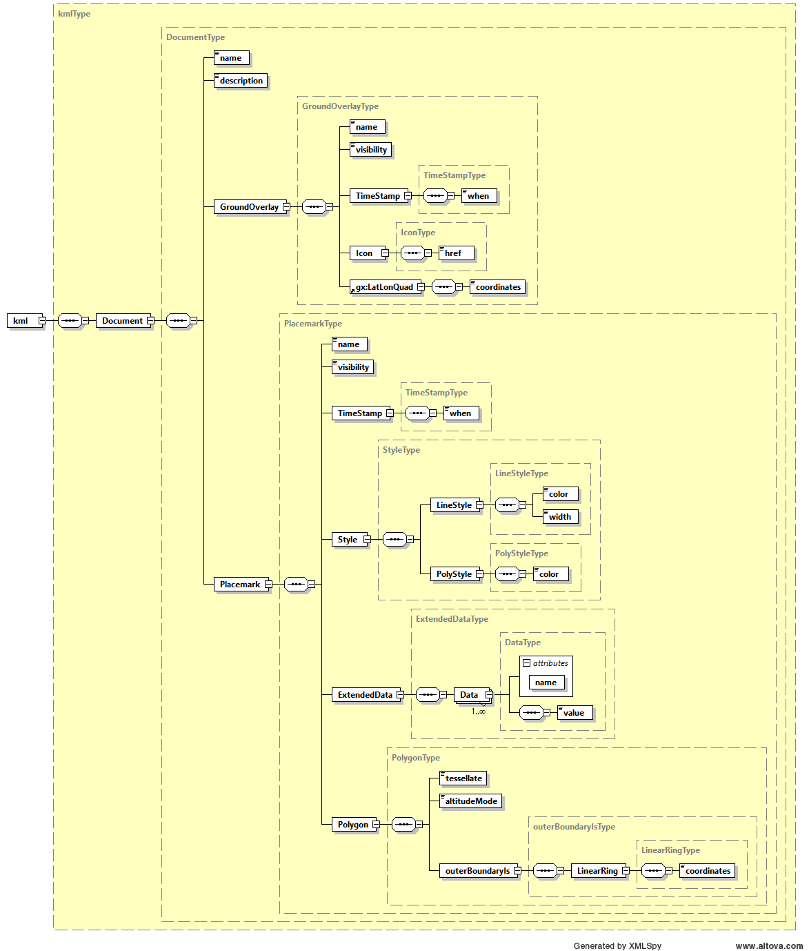
Fig. 17 — Overlay ADS
Table 24 — Overlay ADS
Name |
Description |
Data Type |
Cardinality |
|---|---|---|---|
Document |
Document container for KML components. |
DocumentType |
1 |
Table 25 — Overlay ADS (DocumentType)
Name |
Description |
Data Type |
Cardinality |
|---|---|---|---|
name |
Name of the document. |
|
1 |
description |
Description of the document. |
|
1 |
GroundOverlay |
Contains the parameters required to specify the footprint of the image and overlay the quicklook image on a map. |
GroundOverlayType |
1 |
Placemark |
Contains the metadata associated to the overlay. |
PlacemarkType |
1 |
Table 26 — Overlay ADS (GroundOverlayType)
Name |
Description |
Data Type |
Cardinality |
|---|---|---|---|
name |
Name of the ground overlay. |
|
1 |
visibility |
Specifies whether the feature is drawn in the 3D viewer when it is initially loaded (0: not visible, 1: visible). |
|
1 |
TimeStamp |
Structure containing the time stamp of the overlay that can be used for dynamic visualizations over time. |
TimeStampType |
1 |
Icon |
Structure describing the image file used on the map overlay. |
IconType |
1 |
LatLonQuad |
Structure containing the latitude and longitude coordinates used to position the image overlay on the map. |
LatLonQuadType |
1 |
Table 27 — Overlay ADS (TimeStampType)
Name |
Description |
Data Type |
Cardinality |
|---|---|---|---|
when |
Overlay time stamp in ISO 8601 format (YYYY-MM-DDThh:mm:ss). |
|
1 |
Table 28 — Overlay ADS (IconType)
Name |
Description |
Data Type |
Cardinality |
|---|---|---|---|
href |
A local file specification or URL used to load the desired image and overlay it on the map. |
|
1 |
Table 29 — Overlay ADS (LatLonQuadType)
Name |
Description |
Data Type |
Cardinality |
|---|---|---|---|
coordinates |
A string of 5 lon,lat coordinate pairs which describe the corners of the image. The string is of the form: lon,lat lon,lat lon,lat lon,lat lon,lat The coordinates must appear in the following order: last line first pixel, last line last pixel, first line last pixel, first line first pixel, last line first pixel |
|
1 |
Table 30 — Overlay ADS (PlacemarkType)
Name |
Description |
Data Type |
Cardinality |
|---|---|---|---|
Name |
Name of the placemark. |
|
1 |
visibility |
Specifies whether the feature is drawn in the 3D viewer when it is initially loaded (0: not visible, 1: visible). |
|
1 |
TimeStamp |
Structure containing the time stamp of the placemark that can be used for dynamic visualizations over time |
TimeStampType |
1 |
Style |
Structure describing the stype used to display the placemark. |
StyleType |
1 |
ExtendedData |
Structure containing the metadata associated to the overlay. |
ExtendedDataType |
1 |
Polygon |
Structure containing the latitude and longitude coordinates used to position the image overlay on the map. |
PolygonType |
1 |
Table 31 — Overlay ADS (StyleType)
Name |
Description |
Data Type |
Cardinality |
|---|---|---|---|
LyneStyle |
Line style. |
LyneStyleType |
1 |
PolyStyle |
Polygon style. |
PolyStyleType |
1 |
Table 32 — Overlay ADS (LyneStyleType)
Name |
Description |
Data Type |
Cardinality |
|---|---|---|---|
color |
Line color in 32 bit hex format (AABBGGRR order). |
|
1 |
width |
Line width. |
|
1 |
Table 33 — Overlay ADS (PolyStyleType)
Name |
Description |
Data Type |
Cardinality |
|---|---|---|---|
color |
Polygon color in 32 bit hex format (AABBGGRR order). |
|
1 |
Table 34 — Overlay ADS (ExtendedDataType)
Name |
Description |
Data Type |
Cardinality |
|---|---|---|---|
Data |
Metadata. |
DataType |
1…inf |
Table 35 — Overlay ADS (DataType)
Name |
Description |
Data Type |
Cardinality |
|---|---|---|---|
value |
Metadata value. |
|
1 |
Table 36 — Overlay ADS ()
Name |
Description |
Data Type |
Cardinality |
|---|---|---|---|
tessellate |
Tessellate option. |
|
1 |
|
Altitude mode option. |
|
1 |
|
Polygon outer boundary description. |
|
1 |
Table 37 — Overlay ADS (outerBoundaryIsType)
Name |
Description |
Data Type |
Cardinality |
|---|---|---|---|
LinearRing |
Linear ring description. |
LinearRingType |
1 |
Table 38 — Overlay ADS (LinearRingType)
Name |
Description |
Data Type |
Cardinality |
|---|---|---|---|
coordinates |
A string of 5 lon,lat,height coordinate tuples which describe the corners of the image. The string is of the form: lon,lat,height lon,lat,height lon,lat,height lon,lat,height lon,lat,height The coordinates must appear in the following order: last line first pixel, last line last pixel, first line last pixel, first line first pixel, last line first pixel |
|
1 |